Welcome to the documentation for the 2025 Autonomous Underwater Vehicle (AUV), Type X, developed by the Kennesaw State University AUV team. This documentation provides a comprehensive insight into the design, construction, and the AUV offering a detailed overview of its electrical, mechanical, and software components.
Mechanical Specifications
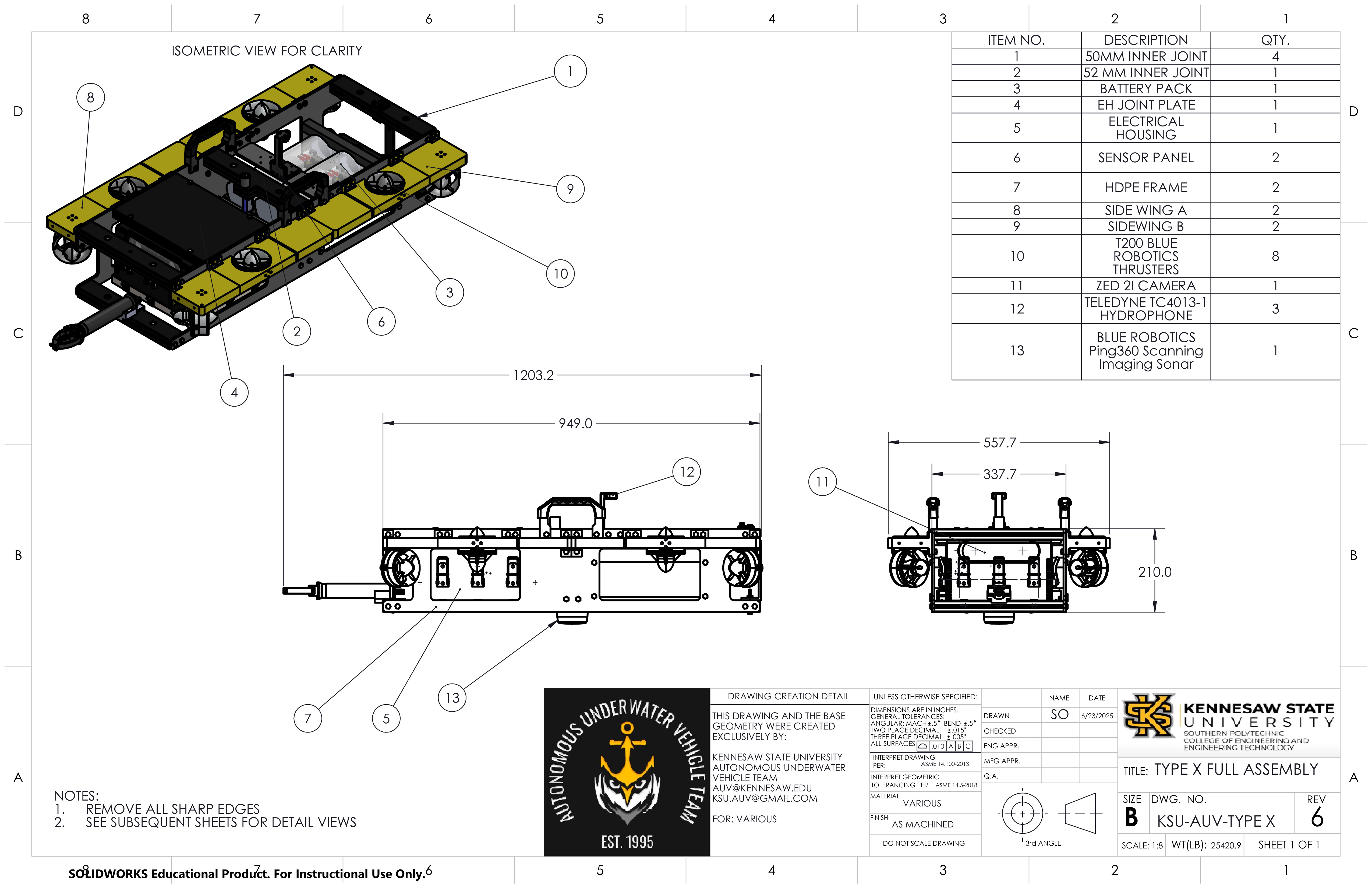
H: 210mm
W: 25.13Kg (55.4 Lbs)
L: 1203.2mm (w/ Arm) --- 949mm (w/o Arm)
W: 557.7mm (w/ Bumpers) --- 337.7mm (w/o Bumpers)
Zeee Lithium-Ion 14.8V 10Ah
6 - (X, Y, Z, Roll, Pitch, Yaw)
8 BlueRobotics T200 Thrusters
Anderson PowerPole
Software & Electrical Specifications
Nvidia ORIN Jetson AGX
STMCubeIDE, Altium Designer
STM32G431KBT6 Microcontroller
Teledyne RESON TC4013
Python, Flask, OpenCV
• ZED 2i
• Anker Power Conference C200
Mechanical Design
Mechanical Changes
The AUV Type X platform has been designed to be our most lightweight, cost-effective, and robust design yet for the 2025 RoboSub competition.
In previous years, the KSU AUV team had relied on 3d printing for supporting elements.
These include mounts and brackets to keep the AUV together. The KSU AUV team has decided to
move forward with 3d printing to create most of the AUV. The main reason for this is that
3d printing can provide a better lightweight and low-cost solution to acrylic methods which
may prove costly and difficult to customize.
The KSU AUV team has taken on a challenge to make 3d printing one of the core manufacturing methods
to easily create components in-house and learn how to make a custom watertight enclosure. A lot
of testing has been conducted across multiple areas to ensure that this challenge ends with success.
CNC Machining and Acrylics
Although the KSU AUV team has made a lot of progress in 3d printing, there are still areas that need to be done with CNC machining and acrylics. The main area that needed a stronger alternative to 3d printing is the power enclosure. This battery housing has been enhanced with acrylic tubes and machined end-plates to create a secure, watertight enclosure. The three power enclosures can be seen in Figure 1 in the center of the AUV.
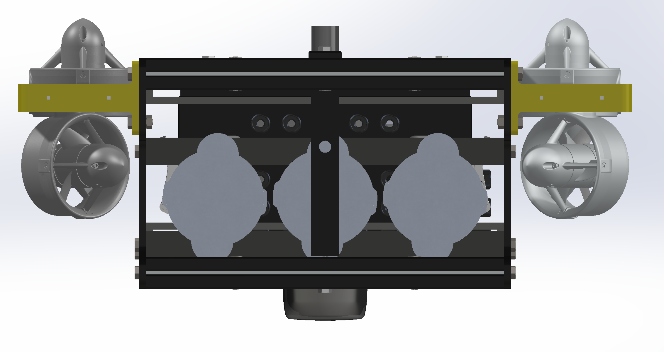 Figure 1: Type X - Front POV
Electrical Design
Electrical Changes
Originally, each module was contained in its own subsystem. This proved to cause issues
with wiring, space, and ease-of-use. This year, the KSU AUV team has made efforts to
centralize all of the systems modules into one large system. This change demanded that the
system overall be redesigned to be modular.
To achieve this goal, the team has specified standards for boards that contain
subsystems. Each of these subsystems will be able to attach to a larger system board called
the motherboard. This motherboard will allow each submodule to easily be added or removed
from the system for ease-of-use. It also hosts the power and signal lines for the submodules
to integrate seamlessly.
Motherboard
The main purpose of the motherboard is to serve as a hub for submodules to easily
integrate with the Orin. This means that both power and signal lines will be hosted on
the board. There are 4 power regulators for 3.3 V, 5 V, 12 V, and 20 V. The first 3 are for
the submodules with the latter being for the Orin. As for signals, multiple PCIe connectors
can be populated. Multiple signal buses run through the connectors to allow for easy
communications.
Since this board hosts power, there is also some safety built into it. This will ensure
that a level of safety is implemented in each system. The motherboard sits between the Kill
Switch board and the Orin. Submodules are contained within the motherboard. A 3d render of
the motherboard can be seen in Figure 1.
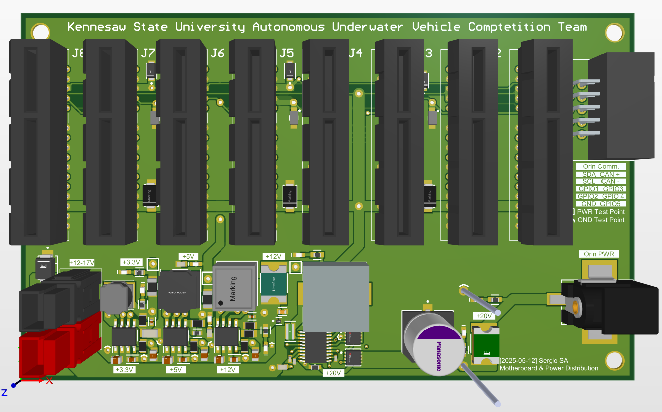 Figure 1: Motherboard Render
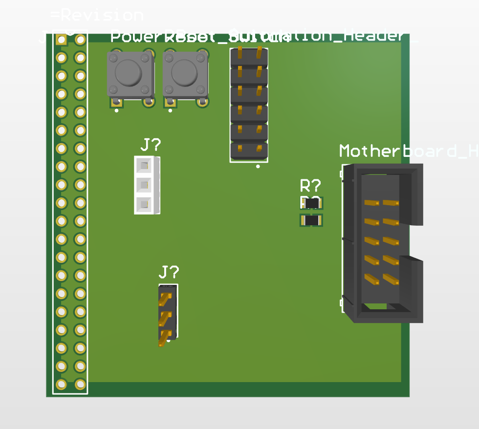 Figure 2: I2C Interface Render
I2C Interface Render
The Orin exposes a number of header pins which are available to be used for various
purposes such as GPIO, I2C, SPI, and CAN. The I2C interface is used to provide a signal
connection between the Orin and the motherboard. This board sits between the motherboard
and the Orin, but is considered part of the Orin as it is connected directly to the header
pins located on the Orin.
This is one of the few boards that are not connected to the Motherboard directly.
ESC Controller
The ESC Controller is a board that provides the Orin with the ability to control the
onboard motors. The controller is not connected directly to the motherboard. Instead,
this board connects to an the ESC Adapter which is connected to the motherboard.
The controller is located nears the ESCs, hence why it is not on the motherboard. To
be supplied with power and data, it interacts with the ESC Adapter. Thus, this
board is located between the ESC Adapter and the ESCs.
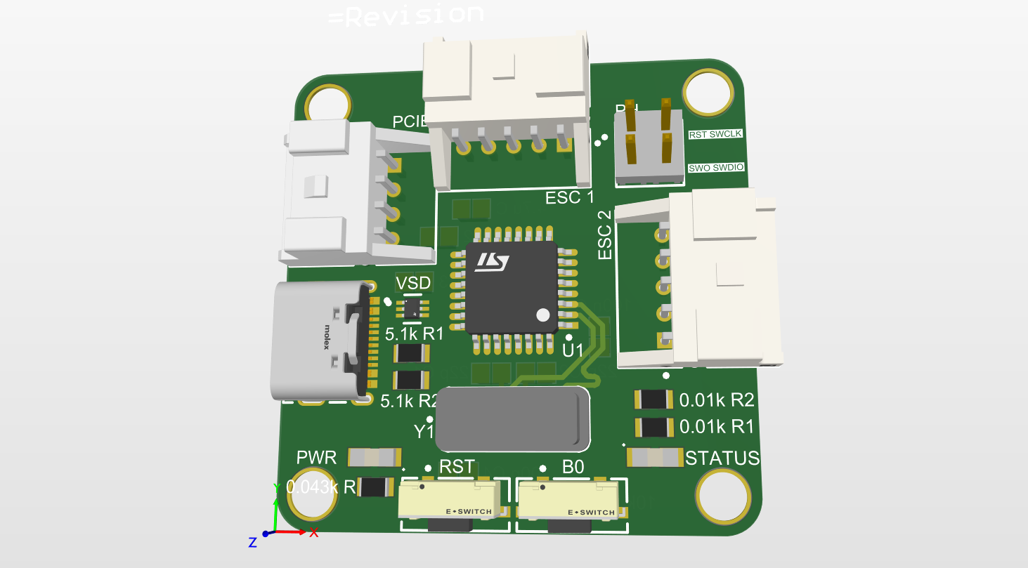 Figure 3: ESC Controller Render
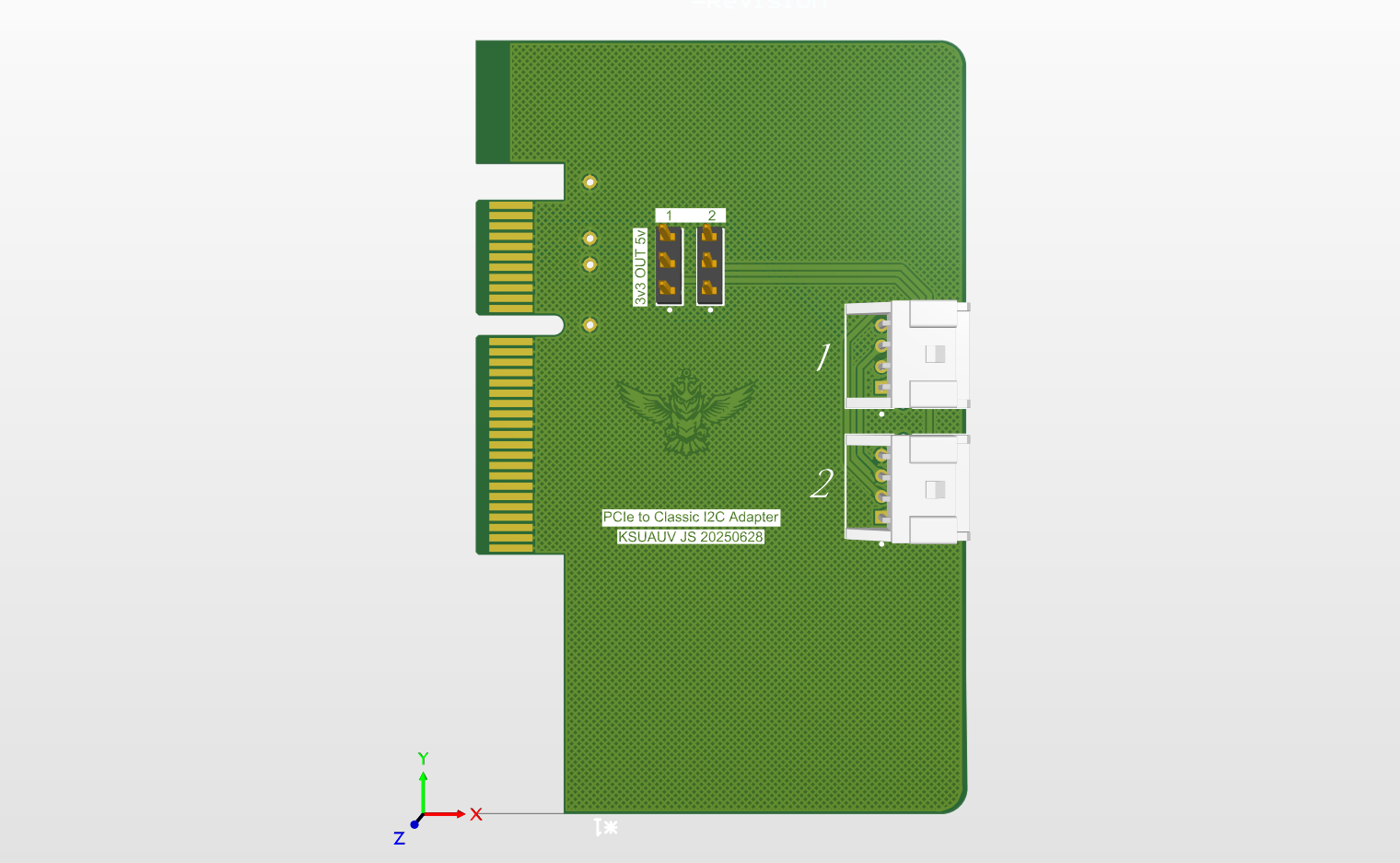 Figure 4: ESC Adapter Render
ESC Adapter Render
The ESC Adapter is the connection between the motherboard and the ESC Adapter. This board slots into one of the PCIe slots on the motherboard and only connects to the ESC controller to provide power and data.
Environmental Module
The Environmental Module provides the Orin with realtime data detected from within the vehicle.
It is able to provide information from an onboard IMU for acceleration, angular velocity,
and orientation. This helps the software team to train their algorithms and react
to sudden changes.
The Environmental Module connects directly to the motherboard. Thus, it recieves
power and communicates with the Orin via the Motherboard.
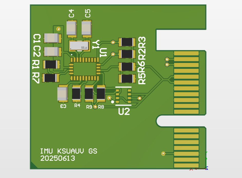 Figure 5: Environmental Module Render
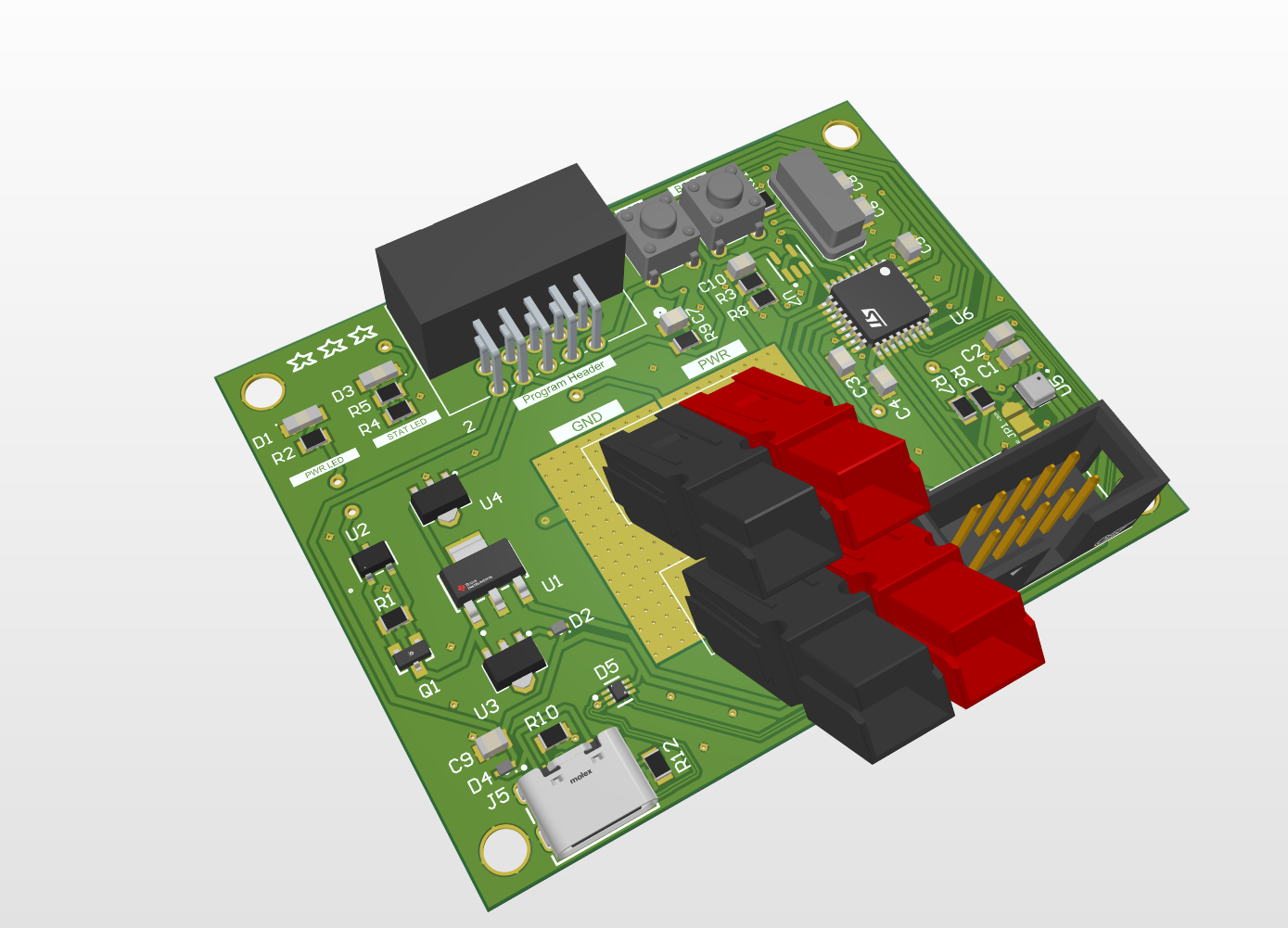 Figure 6: Batter Monitor Render
Battery Monitor Render
To capture data over the battery state, a battery monitor is placed near them.
This provides the team with better information related to the batteries. The batteries are
encased in a sealed metal box which makes it challenging to observe the state. The
battery monitor is the solution.
The battery monitor is not connected to the motherboard. Instead, it is connected to the
batteries and another board hosting a screen which will display the battery state.
Software Design
Check out the full detailed software documentation on the Documentation page!
Background
The developed code consists of several ‘packages’ which perform certain tasks. The primary packages include:
- Flash Handler
- Hardware Interface
- Movement Package
- Camera Package
- AI Package
- Virtual Hardware Interface
The virtual variant is designed for testing within the developed Unity simulation, allowing for the Orin to pilot the sub within it. The regular Hardware Interface allows for the Orin to pilot the physical submersible within the real-world. The other packages remain that same across both real-world and simulation runs.
Flash Handler
The FlaskHandler package uses the Python Flask library to setup a web application that is hosted locally on the Orin. Other processes running on the
Orin are able to access the application, as such several databases are hosted on
this application for the other packages to GET and POST data, allowing for
communication between the different packages.
Databases are accessed by navigating to ”http://127.0.0.1:5000/(database
name)”. Attempting to navigate to a database URL within a browser will result
in a blank page, as the pages aren’t made to visually display the database. The
databases when accessed return a json dictionary, with the key being the column
header and the value being the most recent recorded value for that column
header
Hardware Interface
The Hardware Interface allows for the Orin, the brain of the sub, to communicate
with the physical hardware that makes up the sub. The interface main purpose
is to allow for communication with sensors and motors.
The Hardware Interface is currently divided among two different files, ’HardwareInterface.py’ and ’MPU6050.py’. ’HardwareInterface.py’ is the primary
package for the hardware interface, ’MPU6050.py’ merely providing functionality for the MPU sensor on the sub.
Camera Package
The Camera package accesses two camera. One is a ZED 2i camera, which acts
as the front-facing camera for the sub. The other is an Anker Power Conference
C200 camera, which is used as the anchor camera to allow the sub to observe
what is below it.
The feed from bother cameras is stream to the web application setup by the
FlaskHandler process. The feeds themselves being accessed using ”http://127.0.0.1:5000/video 0”
and ”http://127.0.0.1:5000/video 1”. ’video 0’ contains the feed from the ZED
camera while ’video 1’ contains the feed from the anchor camera.
Movement Package
The Movement Package is concerned with allowing the sub to move in an intelligent way. This is done
by translating inputs received either from the AI or a controller into data that when sent
to the motors will produce the desired results.
The Movement Package also uses another file PID.py which provided a Proportional Integral Derivative (PID). The PID allows for the sub to more intelligently
reach its destination, which we call the set-point. The issue is by default the
sub cannot reach the set-point exactly due to gravity dragging the sub down
and any current pushing the sub away from the set-point. As such to have the
sub remain at a set-point we need to have the motors move the sub.
Sonar Package
The Sonar Package is separate from the Hardware Interface package due to
concerns of unnecessary overhead of including its code in the package and its
need to constantly be operating to be useful.
The sonar used for the package is the Ping360, which has an effective range
of 60 meters ( 175 feet). The current (2025) AUV submersible powers the sonar
using 16.8 Volts, with amperage varying from .67 to .69.
This code operates by sending out a signal at each angle, note that this is
innately in gradians (gradian * .9 = angle) for the ping360. Using the transmitAngle(gradian) we can control the gradian at which the signal is sent out.
This is done for all 400 gradians to get a 360-degree view of the surroundings.
The transmitAngle(gradian) method returns a pingmessage which we can
extract data from, we can then perform operations to get the signal intensity
from it and the distance at which the intensity occurred.
Debug Handler
To track errors and data during runtime the Debug Handler package was created. This package is imported into the majority of packages to provide logging functionality. The DebugHandler.py file itself contains the class definition for a DebugHandler object.